Serial communication: Dwengo & GNU Octave
This tutorial shows several small tricks:
- How to easily compile from the command line using the project Makefile described in my post about command line compilation (extension of Wim's post).
- How to send integers (2-bytes long) over the serial port (1-byte messages).
- How to plot "real-time" the data in the serial port using GNU Octave
 .
.
In case of questions you can ask them here, or you can contact me in the #dwengo channel at irc.freenode.net using any IRC chat client (e.g. Pidgin ![]() ) or a web based client
) or a web based client ![]() .
.
Requirements
Dwengo side
- Same as in the Analog to digital converter: light measurement tutorial.
- Computer with a serial port or USB port.
- One serial cable or a USB-to-serial cable.
Computer side
- Linux OS or compatible.
- GNU Octave 3.6 or higher.
- Octave-Forge package general .
- Octave-Forge package instrument-control .
Introduction
This tutorial shows the basics of sending data to the computer for further analysis (Is the brain of your robot not powerful enough? send data to a PC for analysis!). In this case, we are going to send to the computer the values generated by the light sensor introduced in the light measurement tutorial; and we are going to plot these values using GNU Octave ![]() .
.
Part 1: Dwengo side
First we are going to show how to send sensor values over the serial port. To start you need to follow the light measurement tutorial. Once you have got it working come back and continue from here.
Step 1: Sending analog sensor values over Serial
When we use the serial communication in the Dwengo board the data size is, by default, 8 bits (this is 1 byte). This means that we can send, in a single event, the value of a variable of size 1 byte. In the ansi C language the datatype unsigned char is guaranteed to be at least 1 byte in size and therefore is the type used in serial communication.
What is the biggest integer number that we can store in 1 byte? Easy, we have 8 bits therefore 2^8-1 = 255 is the biggest integer. Now, you may have noticed that the values returned by the light sensor in the light measurement tutorial go up to 1023. This is due to the fact that the digital to analog converter of the board has 10 bits resolution (2^10-1 = 1023). This is more than 1 byte, but less than 2 bytes. So we need to store these values in a datatype that is bigger than unsigned char, the best type would be an unsigned int (ansi C guarantees this datatype to be of at least 2 bytes, i.e. 16 bits).
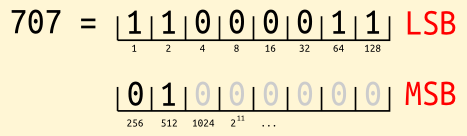
To send an unsigned int over the serial we will break it up in bytes and send one after the other. Below there is an example, the fun number 707 is written in binary and separated in its least significant byte (LSB) and its most significant byte (MSB). In our case the MSB will contain only 2 bits with information, since we will not send values bigger than 1023.
Let's create a C function that does this
The variable data contains the integer to be converted into a suitable serial message msg. Line 5 applies a bit mask to the number to get the LSB. The bit mask is a way of selecting the bits out of a number. In this case we use the mask 0x00ff, which is the hexadecimal ![]() representation of 255, in binary it looks like 1111 1111 0000 0000. 1 That is, the mask will extract only the first 8 bits of the integer stored in data. If data = 707 then msg[0] = 195, that is 1100 0011 in binary. Line 10 extracts the MSB out of data in the same way. Note that we have to shift the bits to store them in msg, since the result of the bit mask has the 16 bits and msg[1] can store only the first 8 (last eight in C). Following our example, msg[1] = 2, since the MSB of 707 is 0100 0000.
representation of 255, in binary it looks like 1111 1111 0000 0000. 1 That is, the mask will extract only the first 8 bits of the integer stored in data. If data = 707 then msg[0] = 195, that is 1100 0011 in binary. Line 10 extracts the MSB out of data in the same way. Note that we have to shift the bits to store them in msg, since the result of the bit mask has the 16 bits and msg[1] can store only the first 8 (last eight in C). Following our example, msg[1] = 2, since the MSB of 707 is 0100 0000.
Time to extend the code of the light measurement tutorial to call this function and send the data over the serial port.
The header of our file is as follows:
Line 4 includes the header file that provides the functions for serial communication. Line 7 defines the time to wait before the next data is sent (in the videos I used 10 milliseconds). Line 10 defines the prototype of our serialization function. Do not forget to include the actual code of the function!
Then comes the main function and we initialize all what is needed:
Line 20 initializes the serial port. Lines 23-27 read a message sent from the computer. Here we are just waiting for a '\r' but in principle you can use this to set configuration values and even send information back to the computer to make sure the messages will be processed correctly.
The main loop is very similar to the one in the light measurement tutorial. We just need to add the serialization of the data and then send the bytes over the serial port. We are sending the LSB first. To make sure the interpretation of the bytes is correct one could send an additional byte like '\r', this could be arranged with the computer during the handshaking. In this case we leave it to fortune :D.
In case you want to see what is being send over the serial port, you can add the following lines.
This will print the two bytes in the LCD display. You can download the full code from the link at the bottom of the page.
Step 2: Compiling the code and programming the board
At this point you are ready to compile your code and program the Dwengo board. If you have follow the instructions in Wim's post and the Makefile post2, just run
make program
This will compile and program your board, so make sure the programmer is connected to the USB port and to the Dwengo board. The following video shows what you should see.
If you did not follow the mentioned posts, you can use the basic instructions for compiling and programming given in this tutorial.
This concludes the tutorial on the Dwengo board side. Any program reading from the serial port will get the measurements of the light sensor. This data will come as two separated bytes so the reading program will have to de-serialize them.
Part 2: GNU Octave
Once you have installed GNU Octave 3.6 or higher (follow these instructions ![]() or these ones if you have Debian
or these ones if you have Debian ![]() ), install the packages general
), install the packages general ![]() and instrument-control
and instrument-control ![]() starting octave and running the following commands (you need internet connection to do this)
starting octave and running the following commands (you need internet connection to do this)
pkg install -forge general instrument-control
And we are ready to go! This is what we are going to obtain
Step 1: De-serializing data
On the Octave side we have to de-serialize the bytes we read from the serial port. The de-serialization just puts together two bytes into one uint16 integer (this is an Octave datatype, it stands for Unsigned INTeger 16bits). The following is a function that does the trick:
Lines 5-8 applies the function bitget(x,1:8) to every element of the data array. This converts the array into a cell (a more general container) of binary numbers (bit arrays). The function cell2mat in line 4 converts the cell back into a matrix. Finally, the function bitpack in line 3 interprets each of the binary numbers as a uint16, that is, it will consume 8 bits to generate a single uint16 number. Save this into the file deserializeInt.m3 or download the code form the bottom of this page (remember to rename the file to deserializeInt.m).
GNU Octave can be integrated with C/C++ very easily. If you have written a de-serealization function in C or C++ let me know so we can port it to GNU Octave and we post it here!
Step 2: The plotting function
In the attachments at the bottom of this page you will find the srl_plot.m file containing the homonymous function. This is the function we call to plot the data. If you look inside the file you will see lot of code, worry not! You just need to execute help srl_plot in the Octave prompt to get an explanation on how to use the function. All parameters are explained there.
The function has the following structure
- Parse options
- Allocate arrays
- Handshake
- Main loop: plot the data
Since 1-2 are irrelevant to this tutorial we will not explain the details. As we said before the handshake (part 3) is super simple and consist only on putting the '\r' character in the serial port to let the board know that it can start sending data. We will look at the main loop of the function in some detail.
First, look at the second video and note that we are calling this function with the following command:
srl_plot ("Deserializer", @deserializeInt, "BufferSize", 60, "Axis", [0 1023])
We are defining three parameters in this command:
- "Deserializer": A pointer (or handle) to the function used to de-serialize the data. In this case we use deserializeInt.
- "BufferSize": The amount of bytes to be read from the serial port before plotting. In the video we were sending approximately 200 bytes every second, a buffer of size 60 will make the plot update every 0.3 seconds. If you use the SAMPLING value in the example code above to get 60 values it will take approx. 6.45 = 60*0.215/2 seconds to update the plot, so you can use smaller buffers for faster updates.
- "Axis": This just says that the figure should have y-axis from 0 to 1023, i.e. the range of our data.
If you look into the function (download it from the bottom of this page, remember to rename the file to srl_plot.m) you will notice that there are two possible main loops depending on the options passed to the function. Both loops do the same, there is only a small difference in how they do it. Let's look into the default behavior:
Line 3 reads bsize (buffer size) bytes from the serial port (pointed by s). The data is stored in the array data and the amount of data read in n. The variable desrl contains a pointer to the deserialization function defined by the user (deserializeInt in our case) and is executed in line 4. After this, data is reduced to half of its size (since 2 values in the serial port represent 1 value of the sensor measurement) so in the next line we update the amount of data read n. Line 6 updates the data to be plotted by adding the new values in a way similar to the news ticker. Lines 8-10 update the plot and the title. The functions tic and toc measure the time passed between successive calls.
And we are done! Enjoy plotting your light measurements and let me know if you have questions, suggestions, improvements or bug reports.
-
Note: ansi C uses big-endian notation, i.e. the first bits are the most significant. In this post we used little-endian notation. ↩
-
You can download makefile.txt at the bottom of the page. Rename it to Makefile (without extension). Make sure you define the variables DWENGOLIB and DWENGOHEAD, pointing to the folder where the dwengo library and the header files are, respectively. ↩
-
In GNU Octave function files and the function inside must have the same name. ↩
- Type:
- Login to post comments
Dwengo vzw ![]() | http://www.dwengo.org
| http://www.dwengo.org ![]() |
| ![]() info@dwengo.org | VAT: BE 0811.397.278 | Paypal Verified
info@dwengo.org | VAT: BE 0811.397.278 | Paypal Verified ![]()
Comments
I hope its compatability is
I hope its compatability is versatile. Got a new android unit from www.spectra.com and been exploring programs related to android. Hope this one will work.
Android
Hi,
You can try downloading the instrument-control package but I do not think it will compile on Android (but I never tried).
There is an Octave for Andriod, but again, I never used it.
Is this available for Android
Is this available for Android OS? It would be great to have an Android device connected to Dwengo.